Bramah Locks and Keys
The complete Bramah lock can be disassembled into the following parts:
- A brass back plate and lock surface plate. From 1798, these surface plates are marked ‘I [or] J. Bramah’ with the monarch’s crown, or ‘Bramah – 14 [or] 124 Piccadilly’ with or without the monarch’s crown. From 1871, these surface plates are marked with either ‘J.T Needs & Co. Down Street, Piccadilly, W’ (1871-c.1875), ‘J.T Needs & Co. 128 Piccadilly’ (c.1875-1887) or ‘J.T Needs & Co. 100 New Bond Street – Late J. Bramah 124 Piccadilly’ (1887-1904) all being accompanied by the monarch’s crown. Blank lock surface plates or those bearing the terms ‘Bramah[s] Patent’, ‘Patent’, ‘Bramah – London’ etc. are copies manufactured after the original patent expired in 1812.
- A turned brass central cylinder containing a number of intricately cut, folded steel sliders, a cylinder back plate with a pin, a central spring, and a brass collet that fits over the pin. Note: Most Bramah box locks have an inset stud on the rear of the cylinder back plate, however, self-locking versions, as well as some standard versions used a cylinder arm instead – see ‘Operating a Bramah Lock’ below for explanation.
- Two halved steel incised locking plates that engage with the central cylinder and steel sliders.
- A turned brass lock mount and front aperture unit.
- A brass or steel sliding bolt, with or without an attached guide plate. Note: Self-locking Bramah locks didn’t require a guide plate.
- A brass sliding bolt support bracket that attaches to the back plate. Note: Self locking Bramah locks weren’t often manufactured to require this bracket.
- A mounted steel spring that attaches to the back plate. Note: For many standard Bramah locks this spring is mounted underneath the sliding bolt however, for the self-locking Bramah locks this spring is mounted to the right of the sliding bolt.
- A brass or steel link plate that engages with the sliding bolt.
- A key with incised bits at varying different depths at the end of the barrel.
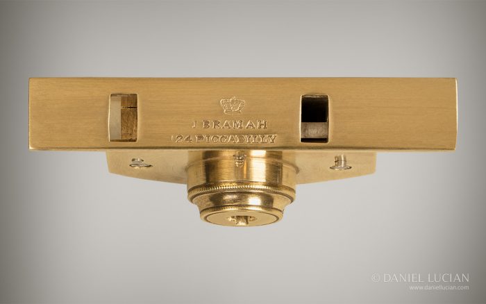
Antique Bramah lock. The stamp of ‘J. Bramah – 124 Piccadilly’ beneath the monarch’s crown confirms that this lock was made by Bramah themselves and not a third party using Bramah’s patent design.
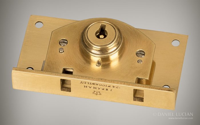
Antique Bramah lock.
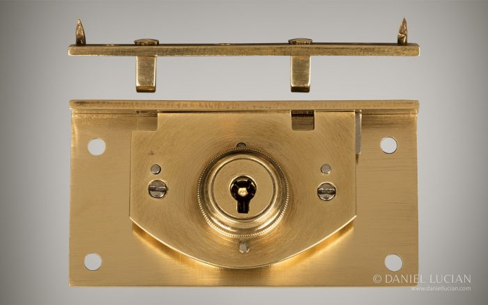
Antique Bramah lock and link plate.
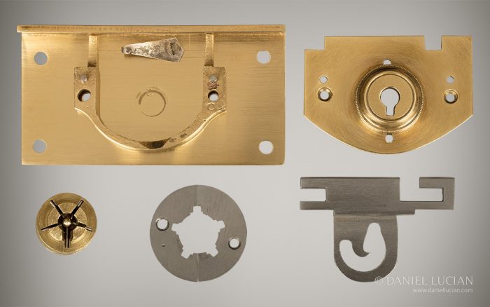
Antique Bramah lock disassembled: View of the back plate, mounted spring, lock mount and front aperture unit, central cylinder, pin, five steel sliders, two halved steel locking plates and steel sliding bolt with guide plate.
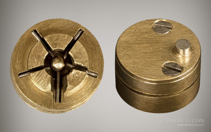
Antique Bramah lock disassembled: Front view of the central cylinder, pin and five steel sliders. Rear view of the central cylinder with stud inset on the cylinder back plate (to engage with guide plate on the sliding bolt).
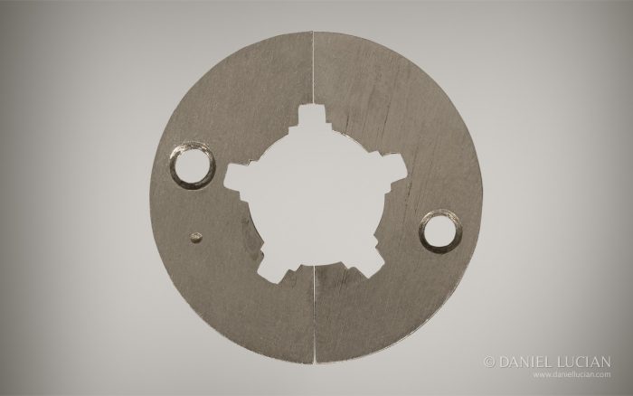
Antique Bramah lock disassembled: View of the two halved steel locking plates.
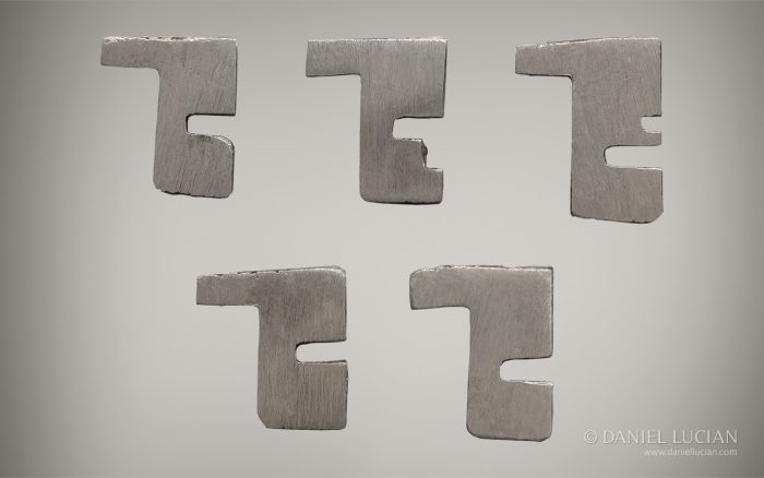
Antique Bramah lock disassembled: View of the five steel sliders.
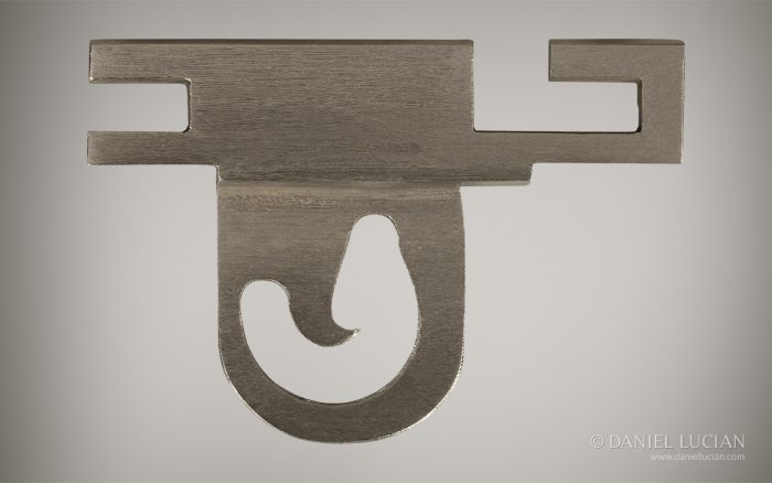
Antique Bramah lock disassembled: View of the steel sliding bolt with guide plate.
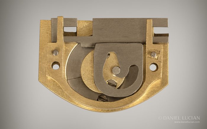
Antique Bramah lock disassembled: Rear view of the lock mount and front aperture unit, two halved steel locking plates, stud inset on the cylinder back plate, and steel sliding bolt with guide plate.
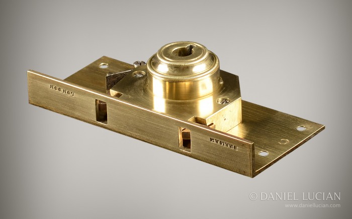
Antique self-locking Bramah patent lock.
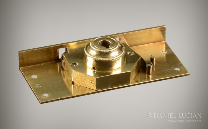
Antique self-locking Bramah patent lock.
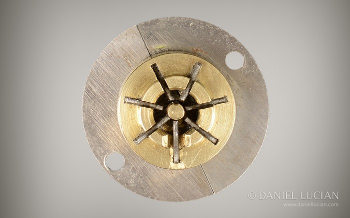
Antique self-locking Bramah patent lock disassembled: View of the two halved steel locking plates, central cylinder, pin and seven steel sliders.
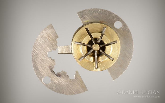
Antique self-locking Bramah patent lock disassembled: View of the two halved steel locking plates, central cylinder, cylinder arm, pin and seven steel sliders.
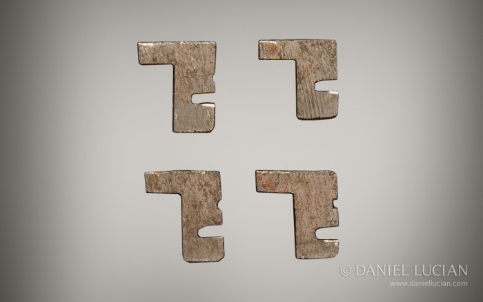
Antique self-locking Bramah patent lock disassembled: Side view of the steel sliders.
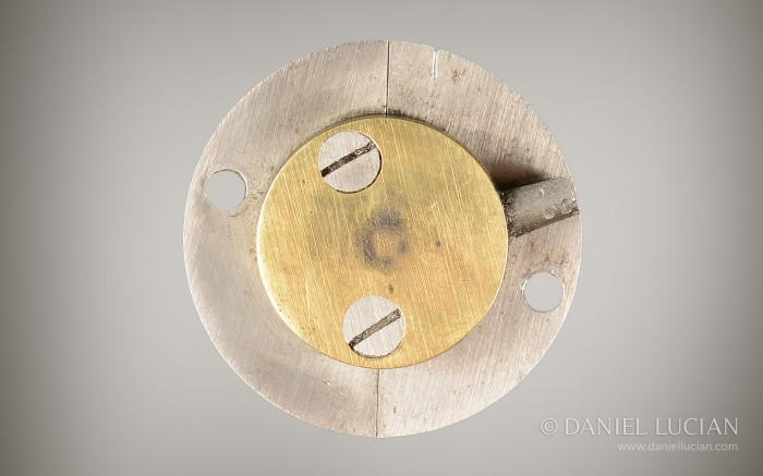
Antique self-locking Bramah patent lock disassembled: Rear view of the two halved steel locking plates, central cylinder back plate and cylinder arm.
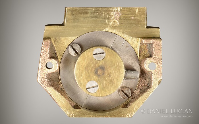
Antique self-locking Bramah patent lock disassembled: Rear view of the lock mount and front aperture unit, two halved steel locking plates, central cylinder back plate and cylinder arm.
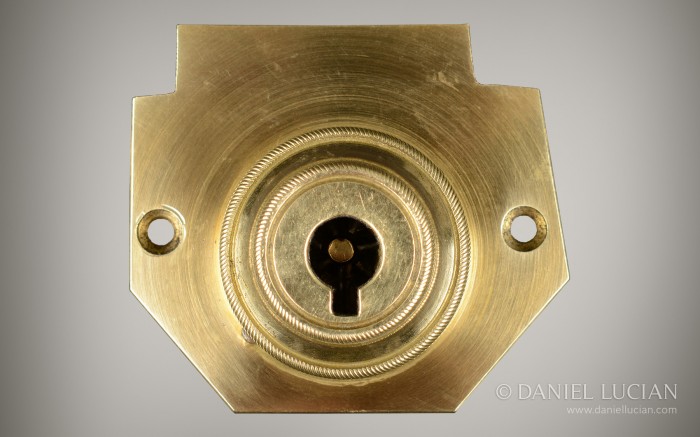
Antique self-locking Bramah patent lock disassembled: View of the lock mount and front aperture unit.
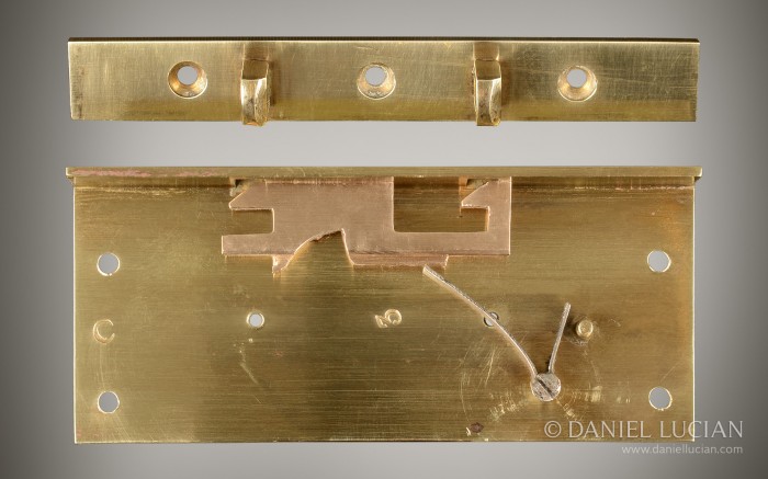
Antique self-locking Bramah patent lock disassembled: View of the back plate, sliding bolt, mounted spring and link plate (top).
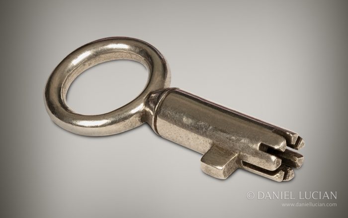
Antique Bramah key: View of the incised bits on the key barrel.

1. Slider. 2. Cylinder. 3. Circular groove in which the circular locking plate (6) engages. 4. Securing screw. 5. Incised notches. 6. Circular locking plate. 7. Pin. 8. Small collet. 9. Spring. 10. Cylinder back plate. 11. Stud. 12. Slider. 13. False notches. 14. Notch.
- The key enters the front lock aperture, guided onto the pin; the incised bits at the end of key barrel engage with the spring-loaded steel sliders. These sliders are incised at exact points to correspond with the incised bit depths of the key. When the key is properly pushed in, the slider incisions all align together, allowing the halved steel locking plates surrounding the central cylinder to be unobstructed. The central cylinder is now rotatable.
- The key can now be turned anti-clockwise, rotating the central cylinder that is either, inset with a stud on the cylinder back plate that engages with the guide plate of the sliding bolt, or, affixed with an arm that engages with an incised ridge on the sliding bolt.
- The sliding bolt is deployed at about the 0-180 degree mark and moves from right to left in most cases. Note: For self-locking Bramah locks, the key is turned clockwise by about -45 to -90 degrees; this action rotates the central cylinder and cylinder arm that then engages with an incised ridge on the lock slider, pushing it back against the mounted steel spring, thus disengaging the lock mechanism. The sliding bolt will automatically spring back into its locked position as soon as the pressure from the key turning action is released.
- With the sliding bolt now in the locked position, the key can complete its anti-clockwise turn back to its initial insertion point, where it can naturally ‘pop’ out from the front lock aperture using the initial spring-loaded mechanism behind the sliders.
- Unlocking the Bramah lock is a simple case of reversing the locking procedure; the key is re-inserted, pressed in, and turned clockwise by 360 degrees to its initial insertion point. The key will again ‘pop’ out from the front lock aperture.
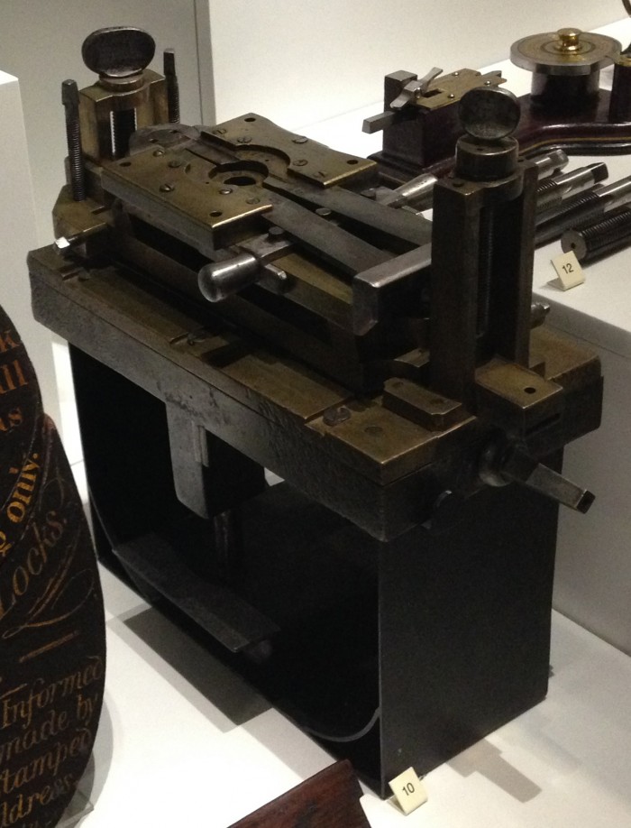
‘Quick Grip’ lock mount vice designed by Joseph Bramah and Henry Maudslay c.1790.
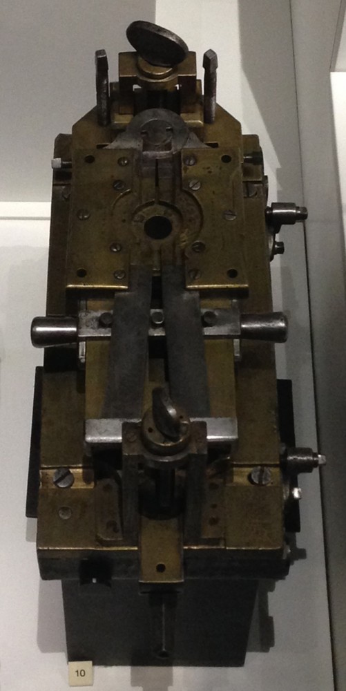
‘Quick Grip’ lock mount vice designed by Joseph Bramah and Henry Maudslay c.1790.
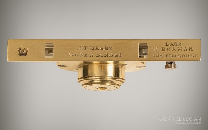
Lock plate stamped with ‘J.T Needs – 100 New Bond St – Late J. Bramah – 124 Piccadilly’. This tells us that this lock was manufactured in, or after, 1887.
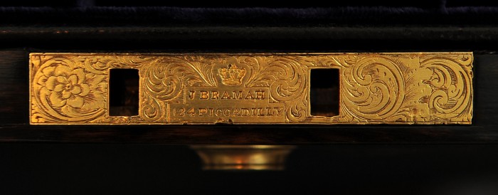
Bramah lock with decorative engraving, stamped with ‘J. Bramah – 124 Piccadilly, London’.
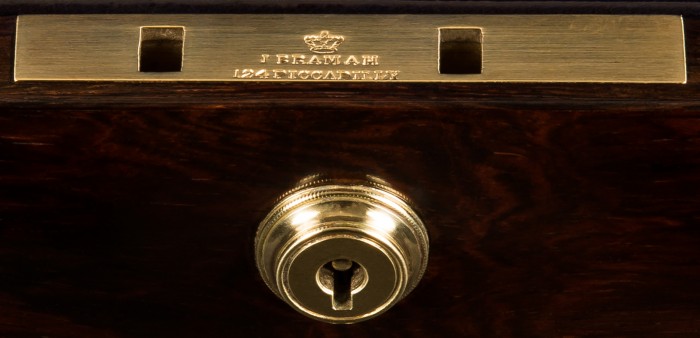
Bramah lock stamped with ‘J. Bramah – 124 Piccadilly, London’.
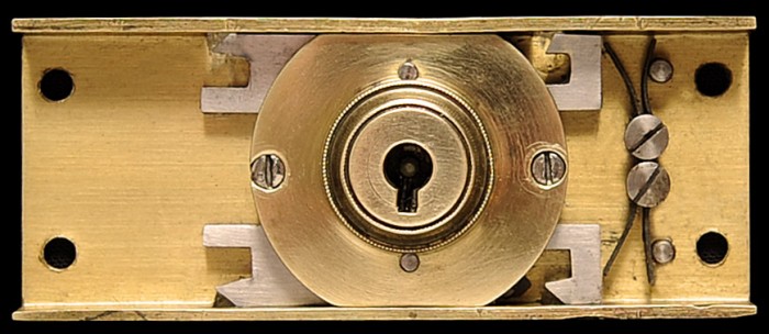
Antique Bramah lock with twin locking mechanism.
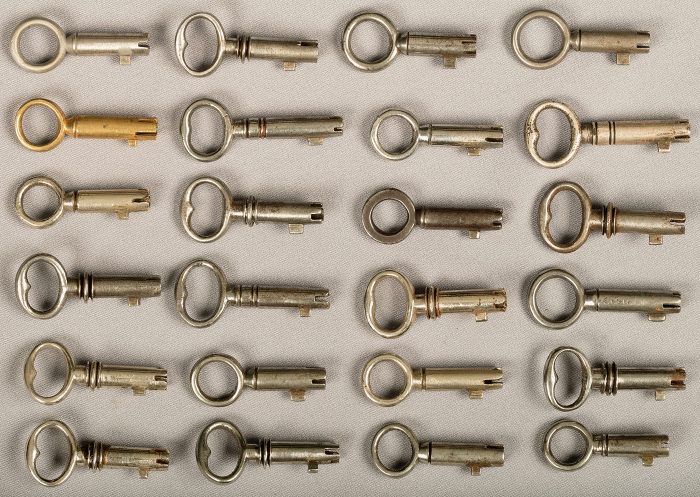
A selection of antique Bramah keys.
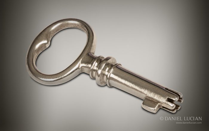
Antique Bramah key.
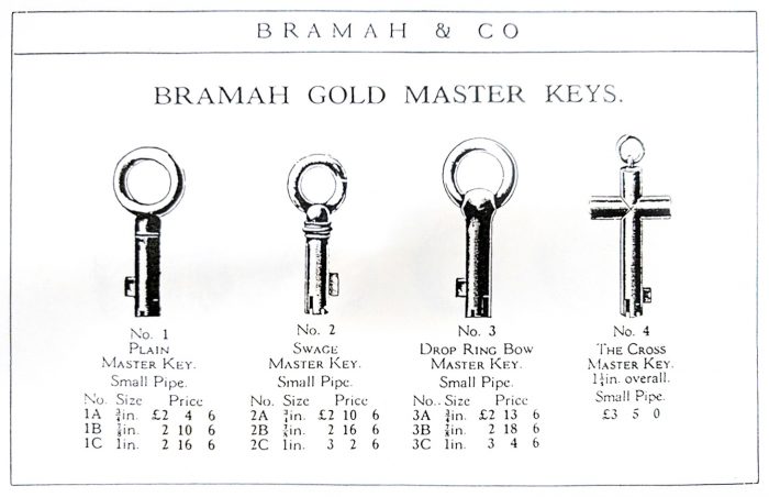
A selection of gold master keys taken from the Bramah & Co catalogue.
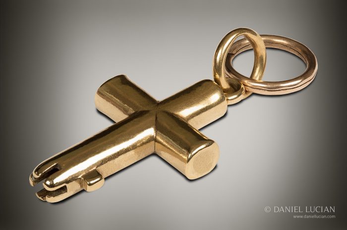
‘The Cross Master Key’ in 18k Gold, by Bramah. These master keys were used to open all the boxes with Bramah locks within that specific household. Whilst each lock had its own specific key, the master key corresponded with additional notches purposely incised on the steel sliders of all the locks, allowing it to operate them.
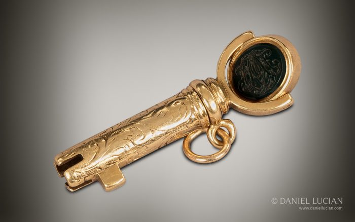
Bramah master key in 15k gold with revolving monogramed intaglio.
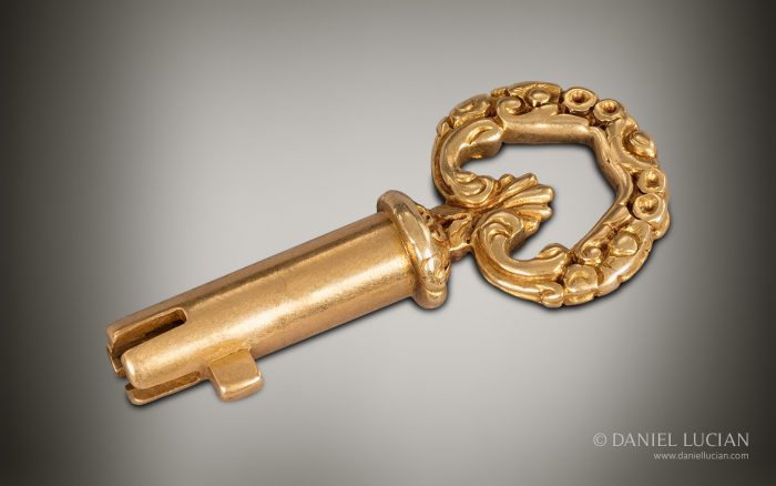
Bramah master key in 15k gold with decorative bow.
 Price On Application